 Today MTP MPO cables are enabling the World by multi-lane densely packed inter and intra connections between Data Storage and Distribution Points. In the coming years, the number of connections utilizing MPO cable structure will increase to ensure a 5G New Radio Metro Transport Network. Along with this, LC to LC Simplex and Duplex connections are common and they are easy to connect. However, when it comes to MTP MPO cable, it becomes not so easy and needs the basic knowledge regarding main features and use cases.
MTP MPO Cables Nowadays, we interchangeably use the terms MTP MPO Cables. However, they are not at all same. MTP cable is an enhanced version of the MPO cable version. Firstly, the MTP connector consists of a removable housing that allows for polish, re-work and change of connector heads. Secondly, they have an advanced mechanical support system to make sure that the cable is not easily broken inside the connector housing. Nevertheless, many MPO has started implementing similar mechanical support and provide breaking resistance from the extensive bending force, but it does not guarantee a removable housing. In high-density cabling environments like data centers, MPO or MTP terminated cables are widely used. Generally, the tight-buffered multi-fiber cable needs to have each fiber individually terminated by a skilled technician. MPO cable which carries multiple fibers is available pre-terminated. Factory terminated MPO / MTP connectors commonly have either 12 fiber or 24 fiber arrays. People generally use the terms MPO and MTP interchangeably and many customers have asked us to clarify the difference between the two. MPO is a fiber connector type whereas MTP is a registered trademark of an MPO connector manufacturer. All MTPs are MPOs whereas all MPOs are not MTPs. MTP is a brand name for an MPO connector that is manufactured. It conforms to MPO specs. MTP stands for Multi-fiber Termination Push-on connector. MTP connectors are highly engineered for high mechanical and optical specs. Few of these features are covered by patents. To the naked eye, you will find very little difference between the two connectors. MPO cable is compatible with each other when it comes to cabling. Main source: https://fibermarts.wordpress.com/
0 Comments
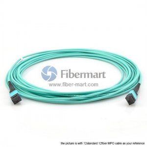 By enabling multi-lane densely packed inter and intra connections between Data Storage and Distribution Points, MTP MPO Cable is enabling the world of today. In the coming years, the Number of connections utilizing the MPO cable structure will increase to ensure a 5G new radio metro transport network. Additionally, LC to LC Duplex and Simplex connections are easy to connect and they are common. However, it is not as easy when it comes to MTP MPO cables. Regarding use cases and main features, it requires basic knowledge.
MTP MPO Cables Nowadays, MTP MPO Cables are interchangeably used. However, they are not the same. An enhanced MPO cable version is MTP cable. Firstly, the MTP connector has a removable housing that allows changing, re-working, and polishing connector heads. To ensure that the cable is not easily broken inside the connector housing, it has a more advanced mechanical support system. Nevertheless, many MPO provides breaking resistance from the extensive bending force by implementing similar mechanical support, but a removable housing is not guaranteed. MPO Trunk Cables To provide and consolidate compact cross-connection across the infrastructure, the MPO Trunk cable is away. Incorporate, telecom, campus, and data center networks, they are widely used. Furthermore, MPO Trunk cables have a very low signal loss and high quality, as well as high-density transmission performance, which is exceptionally provided. Think of 1:1 connections when thinking of MPO Trunk cables, where both sides are 800G, 100G, 40G, 400G, or even200G. That comes out on the other single end of what comes in on one single end. Matching Trunk Cable fiber count to that of the Transceiver or other Equipment on both ends is required to ensure a good connection. The usual MPO cable seen is Loose Tube cables. With a high amount of cladding material, it is a thick cable. For industrial areas and applications, this is used where the cable can experience an outside influence. Ribbon Fiber cables use less cladding and are thin in contrast. Over the same cable run, this allows for greater fiber density. The fragility of the ribbon is the drawback. It must be protected from outside influence and installed securely. Follow our Facebook and Twitter for more information about our product. 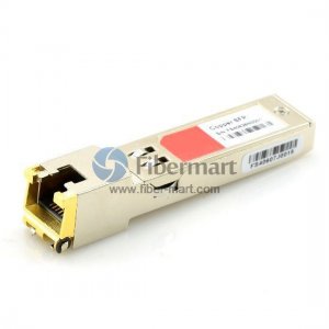 A form of high-speed cable with Small Form-Factor Pluggable Plus on either end, SFP cable like the juniper SFP is a reliable cable. For in-rack connections between switches and servers, they are suitable., SFP cable’s popularity can be attributed for years compared to that Cat5e copper cabling.1000BASE-T has dominated data center interconnection application. However, a significant hindrance in both power cost and consumption is posed by upgrading to 10GE, 40GE, or more. At this point, 10G SFP+ direct attach copper becomes a new favor of Top of rack switching and swoops in.
SFP Cable The lower power, lower cost, and higher density 10 Gigabit Ethernet solution are offered by SFP twin ax cable which replaces connectorized optical fiber and two optical modules with a twin axial copper cable assembly as compared to other cable types. To 10G SFP+ AOC cable and10G SFP+ DAC cable, The SFP cables can be classified. Higher signal transmission capacities, isolation from signal interference, longer transmission distances, and crosstalk are featured by SFP+ AOC. But, as compared to SFP+ DAC, it’s more expensive. Passive DAC and active DAC are present in finisar SFP + DAC. No signal amplification is present in Passive DAC cables have built into the cable assembly for ultra-short reach. Inactive DAC cables signal equalization and amplification built into the cable assembly is present and with a higher price, they have a litter longer reach. Use of SFP Cable 10G SFP cables are commonly used in interconnect applications below 100m as in today’s data center, 10G network is widely deployed. This includes storage to switch or server to switch interconnection in the same rack. Of course, for spine switches, more bandwidth and higher speed are needed. Conclusion Throughput is delivered by many companies with the convenience of play and plug technology, that exceeds those of industry standards. To satisfy the 10G to 100G interconnection demands a variety of high-speed interconnect DAC assemblies are offered by them. The ever-growing need can be met by all direct attach copper cables to deliver more bandwidth cost-effectively. The juniper SFP is reliable. Main source: fibermarts.wordpress.com/ 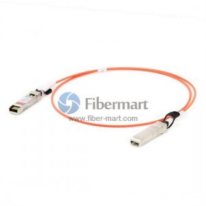 In a variety of industries and applications active optical cable, or AOCs, have largely replaced copper wires to transmit data and signals. Here you will get to know everything about Active Optical Cables, their interfaces, the advantages they hold over copper cables, their end uses, and more.
Active Optical Cables Optical Cables or AOCs serve as cabling technology in improving performance and high-speed transmission active that uses fiber rather than copper between the connectors. AOCs are so much used in applications that include security systems, home theaters, projectors, game consoles, home DVRs, digital signage, as well as industries such as medical, aerospace, and testing companies. In replacing the heavier, bulkier copper cable and helping offset its other shortcomings, AOC cables were made. Difference Between the Active Optical Cables As an alternative to the copper cable, AOCs were primarily created, as it pertains to data centers where copper’s bulky, heavy makeup had made it more difficult to manage and electromagnetic interference provides a tendency in hampering performance. In using Active Optical Cables there are a variety of other benefits, which include: Active, not passive, operation. Make use of fiber, not copper: This characteristic is an important one, so it is necessary in discussing it in greater detail. Fiber patch cable helps in making sure a strong, high-speed signal. It helps in ensuring slim, compact makeup. For example, a fiber wire is usually only about 4.5 mm, whereas a copper wire has a range of 8.5 to 9.3 mm in size. Compared to copper cables AOCs have a smaller bend radius. A signal up to 100 meters is transmitted by AOCs, making for long-distance transmission. AOCs are quite easy to install, use minimal power, and are light in weight. Compared to copper AOCs are more durable; along with this they also come in an armored version which in more demanding environments gives even more protection. Few common places where you will find Active Optical Cables include: Active optical cable Gives High-performance computing centers Digital signatures High bandwidth networks Online gaming Consumer electronics Cloud-based applications A/V services In CATV or other platforms that need high-speed data to operate Main source: fibermarts.wordpress.com/  In telecommunications WDM (Wave Division Multiplexing) is used to optimize and maximize the use of fiber. By multiplexing and demultiplexing multiple data streams with fiber multiplexer, you can achieve this so that over a single fiber they can be transported simultaneously.
With the use of this system, WDM will allow a single fiber to be split into multiple traffic channels. Apart from allowing more flexibility in traffic volume, it also gives flexibility in the transmission of types of data. These traffic channels are the same as the lanes on a motorway with the use of the analogy of a road network, which depending on the amount of traffic at different points of the journey increase and decreases. Multiplexers, at each endpoint, are usually placed within a telecommunications network and are known as terminal muxes. Multiplexing and demultiplexing within the same module are performed for this particular reason they are known as mux/Demux modules. Within the network, these small to medium-sized modular cards do not need a direct power supply. You can buy fiber splitter online. Original WDM systems could carry two bi-directional channels over a pair of fibers; however, there has been rapid evolvement in the technology which has resulted in both the number of data volume and channels per channel increasing significantly. Optical add-drop multiplexers As at the ends of the network, the locations of multiplexers are so that at different points along with the network, traffic also needs to enter and leave the stream much like junctions in a road. Between the two end-points networks have few additional sites which also contain a fiber multiplexer which provides direct connections between it and another site. In different other cases, networks have additional sites that for some need connectivity, but not all traffic. PLC splitter is reliable. Another type of passive module is used when this is the case; an optical add-drop multiplexer, otherwise known as an OADM. Its working is by extracting the wavelengths that are needed for the site and bypassing the rest of the traffic. Due to this ability, you can establish ring, distribution, and access networks. Main source: https://fibermart.blogspot.com/  In a fiber optic communication system, an optical attenuator is an electronic device that is commonly used to decrease the level of power of an optical signal. In fiber optics, we refer to attenuation as a transmission loss. It is the decrease in light signal intensity as per the distance covered by the signal in a transmission medium. In large distances attenuation marks as an important element that limits the transmission of a digital signal traveling.
Optical fiber attenuators employ several principles when it is used in fiber-optic communications. Attenuators that utilize this principle are quite sensitive to the modal distribution ahead of the attenuator. So they need to be utilized at or near the transmitting end as you know. There are three basic types of optical attenuators: the fixed attenuator, step-wise attenuator, and continuously variable attenuator. With negligible or no reflection fixed attenuators reduce light signals by a specific amount. This happens as signal reflection is not an issue and fixed attenuators are known for more accurate data transmission. Necessary elements that are associated with the optical isolator include the flatness over a specified frequency, amount of attenuation, range, voltage standing wave ratio (VSWR), average and peak power-handling capability, performance over a specific temperature, size, and height. In an electronic circuit, fixed attenuators are often used to enhance interstage matching. Many fixed attenuators are available from 5 dB to 25 dB. In rugged plug-in and connector models, the packaging of Mini-Circuits' fixed attenuators is done. In large distances, attenuation marks as an important element. In variable optical attenuators (VOA), with solid-state devices such as the metal-semiconductor field-effect transistor (MESFETs) and PIN diodes, the resistors are replaced. The power ratio is adjusted by the optical circulator between the light beam coming from the device and the light beam entering the device at a changeable rate. Optical fiber attenuators employ several principles when it is used in fiber-optic communications. In fiber-optic communication systems, VOA is usually used to regulate optical power levels so that it can prevent damages in optical receivers which may be due to irregular or fluctuating power levels. Main source: fibermarts.tumblr.com/  The strength of an optical signal that passes through it to a fiber optic cable or open-air is decreased by an optical attenuator. In decibels over a specific distance the signal travels, the intensity of the signal is described. The change that is observed is the strength or amplitude of the signal and not the overall waveform or frequency, so for use in the desired application, the optical signal remains undistorted. Optical attenuators in optical communication systems are often used, in which the transmission loss or attenuation helps with the digital signals long-distant transmission.
By an optical attenuator, the principle of gap loss can be applied it is installed where signals are transmitted so to the optimal level over a given distance, the signal intensity is lowered. The signal strength is not lowered enough by the attenuators installed elsewhere along with the optical fiber, but to compensate for some devices you need to utilize signal absorbing or reflecting components. Telling about the type of equipment in which it can be installed, the attenuator consists of a box-like structural or cylindrical shape. Sometimes found in an electronic circuit, the fixed variety of optical attenuators does not reflect light signals to decrease their intensity. It is used where high accurate data transmission is needed. By the amount of power, the optical isolator function is determined and can be handled in addition to important variables such as performance versus frequency range and temperature. Resistors are used by many optical attenuators, but a variable optical attenuator utilizes metal-semiconductor field-effect transistors or other solid-state components. On a printed circuit board a variable optical attenuator can be mounted, or in test devices such as an optical power meter, it can be used. With an optical fiber cable, many attenuators are installed in-line just to adjust the transmitted signal accordingly. Online fiber splitter is sold by many retailers and manufacturers so just by reading the product specifications one can assess their characteristics. Things that need to be considered include its overall dimensions and the type of environment it can operate, how much attenuation it provides, as well as average and peak power the device can tolerate. For more information, please visit: www.fiber-mart.com/  In applications spanning telecommunication and data communication fiber patch cable is seeing broad adoption. Fiber patch cord represents by far the most sufficient and prevalent bandwidth feeder as many businesses and enterprises take greater advantages from it. So, having some basic understanding of the fiber patch cord will be very helpful.
Fiber optic patch cable is often referred to as fiber optic patch cord or fiber jumper cable, fiber optic patch cords are the simplest fiber optic elements. However, in a fiber optic system, they are used to connect various components and instruments. Their characteristics in terms of loss and aging tell you about the overall performance of the system. In principle, there should be almost zero loss when two fiber patch cords are connected and when the fibers are identical. There is the availability of Patch cords with different types of fibers and different connectors. Fiber Patch Cord A fiber patch cord or fiber jumper or fiber patch lead, terminated with fiber optic connectors (LC, SC, MTRJ, ST, etc.), fiber patch cable is a length of fiber cable that at each end. To an active optical cable or other telecommunications/computer device, the connectors allow the fiber optic patch cord to be rapidly connected. For indoor use, like in server rooms or data centers, fiber jumper is a key player. Fiber patch cord has ranked the best choice for applications where conventional copper cables fail to reach as they feature superior adaptability, improved security, and excellent reliability. Common Types of Fiber Patch Cords Based on different specifications and standards, from the perspective of connector type, fiber cable mode, polarization maintaining, transmission mode, jacket type, and polishing type the categorization of common fiber patch cords is done. Mode of Fiber Cable: Single Mode or Multimode The mode of fiber patch cables tells that how within the fiber the light beams travel. Single-mode and multimode are the two fiber cable modes. Types of Fiber Patch Cord and How to select one In the market, you will find many fiber optic patch cords. It is mainly divided into common fiber patch cord types and special patch cord types in this explanation. Original source: www.fiber-mart.com/ 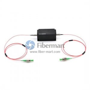 You may learn about LC fiber patch cables or MTP/MPO fiber cables while talking about fiber optic patch cables. Apart from these cables, there are some special fiber patch cables, such as polarization maintaining patch cable and mode conditioning patch cables that have been introduced in the previous article.
PM Patch Cables At first, let me check the basic definition of the PM patch cables. On a high precision, butt-style connection technique is polarization maintaining isolator is based. By using male connectors with a positioning key and a bulkhead female receptacle with a tight tolerance keyway the PM axis orientation is maintained, and hence ensures good repeatability in extinction ratios and insertion losses. Need of PM Patch Cables Stresses are induced in the fiber when a normal fiber is bent or twisted and the polarization state of light will be changed by the stresses traveling through the fiber. The final output polarization varies with change in temperature or position of the fiber. Polarization maintaining circulator is developed to solve this problem. For two perpendicular polarizations traveling through the fiber, inducing a difference in the speed of light will make these fibers perform. Within the fiber, this birefringence creates two principal transmission axes which are known as the fast and slow axes of the fiber. Provided the input light into a PM fiber is linearly polarized and orientated along with one of these two axes, then from the fiber, the output light will remain linearly polarized and aligned with that axis, even when it is subjected to external stresses. To maintain polarization to at least 30dB at 1550 nm a one-meter-long connector’s patch cord constructed with PM fiber should be properly used. How well a PM fiber maintains polarization will depend on the input launch conditions into the fiber. The alignment between the polarization axes of the light with the slow axis of the fiber is the most important factor. Conclusion For transmission of light needing the PM state to be maintained, in polarization-sensitive fiber optic systems PM patch cables are used widely. With various connector types, many companies provide polarization maintaining patch cables. 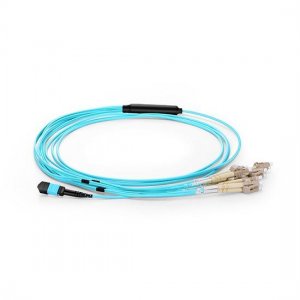 For all networking and device needs like 40G modules and different applications, MPO/MTP fiber cable is specially designed. Around precision molded MT ferrule, it uses a high-density multi-fiber connector system built, which are also available in UPC and APC polish. Both multimode and single-mode applications are supported by it and optional lengths are also available. There are two main MTP/MPO cable types: MTP/ MPO trunk cable and MPO/MTP harnesses cables. The following article will provide a brief introduction to them.
MPO/MTP Harnesses Cables The MPO/MTP Harnesses cable on one end has MPO/MTP and on the other end has single-fiber connectors and in LC, SC, MTRJ, and ST single-fiber connector interfaces are available that too in forms of simplex or duplex channeling. For migrating from legacy 10G to a higher speed 40G/100GbE it provides a reliable, cost-effective cabling system. For many device needs like 100G modules, including CFP, CFP2, and CFP4 series they are highly suitable. In SM (OS2), MM (OM3/OM4) MPO/MTP harnesses cable is available. According to your own needs and with the selection of 12/24/72 fiber cores you can select a suitable fiber. The design of MPO/MTP breakout cable caters to up-scaling needs and future technology growth. It is a perfect solution that in all areas of the Data Center covers all fiber optic cabling needs. MPO/MTP Standard Trunk Cables In data centers and other high fiber environments, these cables are used to facilitate rapid deployment of high-density backbone cabling thereby reducing network installation or reconfiguration. With 6 MPO/MTP connectors a 72-fiber MPO/MTP trunk cable can be terminated which are generally manufactured specifically for multi-fiber loose tube or ribbon cable. For Data Center Applications the MPO/MTP Trunk Cable is designed. These cables can even interconnect ruggedized MPO breakout cable, cassettes, or panels hence allowing for flexibility in case of any change in decision that is made to change the connector style in the patch panels. With the new connector style, new cassettes can be installed on the cross-connect side of the patch panel even without finding the need to change the connector on the cable trunk. Get the best deal online. |
AuthorWrite something about yourself. No need to be fancy, just an overview. Archives
June 2024
Categories
All
|
 RSS Feed
