 Passive PM Fiber Splitter is the components that separate the fiber and its signal. These networking components are fully passive, which means they do not require any power, climate control, or maintenance.
A signal from the Aggregation Switch is sent via fiber. When the light reaches a Passive Optical Splitter, its mirrors, and glass split it into two, three, or more fiber strands. The splitter divides the input signal's optical strength evenly among many output strands. A splitter is used for a variety of purposes, including connecting several optical receivers, dispersing signals to different places, and connecting a single transmitter to multiple receivers. Fiber optics has changed the telecommunications business during the last few decades. Optical splitters have been useful in passive optical networks because they allow several subscribers to share a single PON interface. Understanding Fiber-Optic Splitters PM Fiber Splitter is an affordable and dependable option for a variety of fiber optic applications. A fiber optic splitter, sometimes called an optical splitter, fibre splitter, or beam splitter, is an integrated waveguide (which provides wide bandwidth and minimizes loss in a high-frequency application) optical power distribution device that can split an incident light beam into two or more light beams and vice versa, with multiple input and output ends. Optical fibers are a unique type of optical waveguide. A waveguide is a material structure that allows light to travel while inhibiting expansion in one or two dimensions. Fibers are two-dimensional waveguides that may function as flexible light pipes. The two most common types of fibre optic splitters are FBT (Fused Biconical Taper) and PLC (Planar Lightwave Circuit) splitters. FBT splitters are manufactured by fusing and stretching two or more fibers together. They are relatively simple and inexpensive to make. In contrast, a PM PLC Splitter divides the signal using a flat waveguide constructed of silica or other materials. They are more difficult to construct than FBT splitters, but they can handle a greater number of splits, usually up to 1:64 or higher. PLC splitters are also more dependable, with better insertion loss and wavelength homogeneity.
0 Comments
 Polarization Maintaining Patchcord is a form of single-mode fiber. Normal single-mode fibers may convey randomly polarized light. However, PM fibers are intended to propagate just one polarization of the incoming light.
Polarization-maintaining fibers retain the polarization of linearly polarized light waves released into the fiber throughout transmission, with little or no optical power cross-coupling between the polarization modes. This polarization maintenance function is critical for some fiber optic components, such as external modulators, which need polarized light input. This property is obtained during the production process by creating stresses in the material itself. There are two types of polarization-maintaining fiber (PMF) available: linear polarization-maintaining fiber (LPMF) and circular polarization-maintaining fiber. Polarization Maintaining Optical Switches (PM Fiber Switches) are passive components with two or more ports that selectively transmit, reroute or stop optical signals in an optical fiber transmission line. They may retain a well-defined state of polarisation (SOP) for light. Fibre optical polarization-maintaining (PM) switches are widely used in telecommunications, networking, and sensor and measurement applications. Polarization Maintaining Optical Switch is a passive device that opens and closes optical circuits or switches light beams from one fiber to another. Polarization-preserving optical switches may maintain a well-defined state of polarization (SOP) of light by using panda PM fibers (PMF). Polarization applications for fiber maintenance PM optical fibers are utilized in unique applications such as fiber optic sensing, interferometry, and slab dielectric waveguides. PM fibers are projected to be employed in coherent or long-distance bidirectional optical transmission systems. They can also be utilized in transmission applications that need the polarization plane of the optical signal, such as transmission lines for optical sensors and coupling for optical-electrical integrated circuits. Polarization Maintaining Patchcord are employed in lithium niobate modulators, Raman amplifiers, and other polarization-sensitive devices to retain the polarization of incoming light and minimize cross-coupling between polarization modes. They may retain a well-defined state of polarisation (SOP) for light. Fibre optical polarization-maintaining (PM) switches are widely used in telecommunications, networking, and sensor and measurement applications. 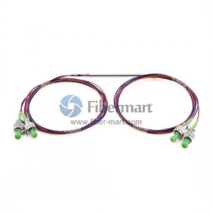 Fiber optics is a key technology in the field of contemporary telecommunications and data transmission, allowing information to be sent quickly and effectively across great distances. Crucial parts like fiber couplers and Fiber Trunk Cable, which are sometimes taken for granted but are essential to guaranteeing smooth communication and data transfer are at the core of this technology.
Fiber Couplers Devices called fiber couplers, often referred to as splitters or Fiber Coupler, are made to divide or combine light signals in optical fibers. Directing optical signals from one or more input fibers to one or more output fibers is their main duty. Through this method, optical signals may be distributed over several routes, enabling a wide range of applications, including optical sensing, wavelength division multiplexing, and signal monitoring. Planar lightwave circuit (PLC) couplers, polarization-maintaining couplers, and fused biconical taper (FBT) couplers are just a few of the variants available for these devices, each designed to meet unique needs and performance standards. In contrast, PLC couplers are perfect for high-density optical networks because of their superior performance and scalability. Fiber Trunk Cables Fiber Trunk Cables are an essential component of optical network architecture that supports the functions of Fiber Couplers by enabling smooth data transfer between network nodes. These cables offer high bandwidth and low latency connection over long distances by bundling many optical fibers under a protective sheath. In several network topologies, such as mesh, point-to-multipoint, and point-to-point, fiber trunk cables are essential. They facilitate the construction of dependable communication channels in corporate, data center, and telecommunication networks by acting as the main means of data transmission between network switches, routers, and other active components. Fiber couplers and Fiber Trunk Cable work together to support a wide range of applications in many sectors. These parts of the telecommunications system make it easier to provide high-speed internet services, giving both consumers and companies seamless access. They act as the foundation of cloud architecture in data centers, facilitating quick data transfers between servers and storage units. Additionally, the possibilities of Fiber Couplers and Trunk Cables continue to be expanded by continuous improvements in fiber optic technology. 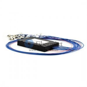 There is a continuing need for high-speed, dependable, and affordable network solutions in the fast-paced world of telecommunications. To satisfy these needs, the photonic layer circuit PM PLC Splitter has become more important. They offer several benefits that increase the efficacy and efficiency of communications networks.
Small & Space-Saving Design PLC splitters are perfect for usage in confined spaces and congested telecommunication cabinets because of their small size and space-efficient construction. Network operators may optimize space use with their tiny form factor, resulting in more efficient and well-organized network deployments. Elevated Division Ratio The capacity of PLC splitters to produce large splitting ratios—that is, to divide optical signals into many pathways without compromising signal quality—is one of its noteworthy features. PLC splitters provide flexibility for a range of network topologies and deployment circumstances by supporting split ratios as high as 1:2, 1:4, 1:8, and even higher. Minimal Insertion Loss To guarantee dependable data transfer in telecommunications, signal strength maintenance is essential. Because PM Fiber Splitter has a low insertion loss, they divide optical signals with the least amount of signal attenuation possible. This feature aids in maintaining signal integrity and overall network performance. The capacity to use broadband PLC splitters may function across a large range of wavelengths because of their exceptional broadband capacity. Because of their adaptability, they can be used with a wide range of optical systems, thus network operators may deploy them in a variety of applications without having to take wavelength specificity into account. Dependability and Sturdiness Reliability in telecommunications is critical. PLC splitters are made with premium materials and manufacturing techniques, which provide strong and long-lasting parts. Because of its dependability, there is less need for regular maintenance and less downtime due to constant performance throughout time. The ability to scale Scalability becomes an important factor as network requirements change. Because Polarization Maintaining Splitter are scalable, network operators may easily add more splitters to their systems to meet the increasing need for data transmission capacity. Next: The Role of Fiber Adapter and LC Pigtail in Optical Networking 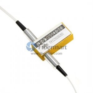 Fiber optics is a practical instrument that is frequently utilized in the domains of engineering and applied sciences for the transfer of data across great distances. Optical fibers are translucent, bendable strands of silica, or pure glass. Fiber optic cables, which are as thin as human hair, serve as a waveguide to carry light between the two ends of the strand. Due to their reduced transmission loss and resistance to electromagnetic interference, these cables are favored over metal wires. A clear core and a transparent cladding material with a reduced index of refraction are the basic components of optical fiber. Total internal reflection keeps light inside the core. The fiber now functions as a waveguide. You can buy fiber polisher online.
The caliber of the fiber and the clarity at either end of the transmission line is crucial to the effectiveness of fiber optics. The cut ends of the wires need to be polished smoothly to maximize efficiency and data transfer rate. The development of fiber optic polishing devices has advanced significantly during the past several years. Companies that rely on these cables now have access to a complete industry that caters to their demands. Within the fiber polishing machine, some businesses polish fiber ends on-site, and others design and provide the highly specialized polishing equipment needed for the job. When measuring elements like apex offset, the radius of curvature, fiber protrusion, back reflection, and under-cut, optical fiber polishing machines are capable of the tight tolerances and precise repeatability needed to continuously deliver outstanding manufacturing outcomes. Yield and throughput are two crucial elements to consider when choosing optical fiber polishing equipment. Yield is a measure of consistency and quality. Productivity is gauged by throughput. The greatest of these tools enables platen force, speed, and time adjustments to meet exact requirements and accurately polish fiber optic connection ends in a repeatable, dependable way. For a variety of uses, specific polishing materials and fiber optical switch have also been created in addition to highly developed and programmed polishing equipment. These substances, sometimes known as abrasive films, are made to produce extremely exact polishing results.  The form factor of cisco QSFP28 transceivers is the same as that of the QSFP optical transceiver. The latter supports 40G, whilst the former only provides 4 electrical lanes that may be utilized as 4x10GbE or 4x25GbE. According to all of this data, a QSFP28 module splits either 4x25G or 4x10G lanes, depending on the transceiver being utilized. The SFP28 transceivers, which run at a slower 10G speed and accept SFP+ transceivers, exhibit the same behavior.
Both QSFP+ and QSFP28 optics may often be used with a 100G QSFP28 port. The QSFP28 optics can run 4x25G breakout, 2x50G breakout, or 1x100G if they support 25G lanes. The QSFP+ optic can operate 4x10GE or 1x40GE since it supports 10G lanes. Keep in mind that there are Twinax/AOC and single-mode and multimode (SR/LR) optical transceivers available if you employ QSFP transceivers in QSFP28 ports. QSFP28 Optics Cannot Ever Be Used on QSFP+ Port SFP+ cannot automatically negotiate to support SFP modules, and cisco QSFP cannot be utilized on a QSFP port. It boils down to the optic and the port, and vice versa, according to the rule regarding combining optical transceivers with various speeds. The form factor and both ends of the two modules must be compatible. Additionally, the port speed must match or exceed the optical speed. When selecting the best MTP trunk cable for a 40G QSFP+ SR4/CSR4 transceiver connection, there are several other aspects to take into account in addition to employing an MTP 8-fiber or MTP 12-fiber trunk cable. Conclusion In conclusion, QSFP+ modules can be utilized on QSFP28 ports however QSFP28 transceivers are unable to transmit 100Gbps on QSFP+ ports. Don't forget to set up your switch before utilizing the QSFP optics on the QSFP28 port. We must select a female-female MTP trunk cable if we wish to properly link a 40G QSFP+ SR4 transceiver to another 40G QSFP+ SR4 transceiver. We must choose a type B MTP 8-fiber or MTP 12-fiber trunk cable under the IEEE 40GBASE-SR4 requirements. You must make sure that the connections on both ends are identical and that there are no problems with manufacturer compatibility to guarantee a smooth network transfer. You can opt for cisco SFP. Follow our Facebook and Twitter for more information about our product. 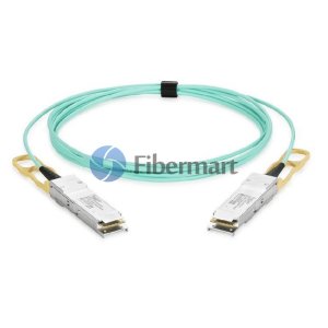 How Do QSFPs Work?
Quad Small Form Factor Pluggable or QSFP cable is the agenda today. All of the standards have undergone vendor verification. All the modules, connections, and cages have been made available by the vendors. It can handle 40 Gb/s per port. Four separate channels can each be supported by a port. The maximum speed per channel is 10 Gb/s. The type of speed we anticipate will soon be supported by optical modules. The combination of QSFP connections and cages today allows for 10GB/s operation in both backplane and short-reach applications. Actuality of QSFP The QSFP module provides the greatest pluggable bandwidth density available on the planet. The format standard is constantly changing, allowing for larger data speeds. The maximum speed is 4x28 Gbit/s. It also goes by the name QSFP28. You can buy DAC cable online. Different QSFP Types Right now, each type of QSFP transceiver has a different transmitter and receiver. It aids the user in choosing the proper transceiver for each link. Then, it provides, across multi-mode or single-mode fiber, the required optical reach. Today's market offers a variety of QSFP module classifications. Among them are: · Four 1 Gbit/s QSFPs: It consists of four channels with the capacity to transport DDR InfiniBand, Gigabit Ethernet, or 4GFC. In the original QSFP document, all of this information is mentioned. · Four x 10 Gbit/s QSFP+: A modified QSFP transceiver is this one. It provides four 10 Gbit/sec channels that can transport QDR InfiniBand, 10GFC Fiber Channel, or 10 Gigabit Ethernet. An advantage of adding 4 channels and merging them into one 40 Gigabit Ethernet link has been offered by the suppliers. Typically, it is only intended for use with 40G Ethernet, Infiniband, and other communications protocols in data centers. · Four x QSFP+ 14 Gbit/s (QSFP14): This QSFP+ is solely intended for basic use. It doesn't always follow that it has no worth. It is intended to enable the complete capability for FDR InfiniBand, SAS-3, or 16G Fibre Channel. · Four QSFP+ 28 Gbit/s ports (QSFP28 cable): It is intended to handle 32G Fibre Channel, EDR InfiniBand, or 100 Gigabit Ethernet. Direct-attach cables can also be used to affix such transceivers. In this manner, four separate 25 gigabit Ethernet ports may provide 100Gbe. Follow our Facebook and Twitter for more information about our product.  Today MTP MPO cables are enabling the World by multi-lane densely packed inter and intra connections between Data Storage and Distribution Points. In the coming years, the number of connections utilizing MPO cable structure will increase to ensure a 5G New Radio Metro Transport Network. Along with this, LC to LC Simplex and Duplex connections are common and they are easy to connect. However, when it comes to MTP MPO cable, it becomes not so easy and needs the basic knowledge regarding main features and use cases.
MTP MPO Cables Nowadays, we interchangeably use the terms MTP MPO Cables. However, they are not at all same. MTP cable is an enhanced version of the MPO cable version. Firstly, the MTP connector consists of a removable housing that allows for polish, re-work and change of connector heads. Secondly, they have an advanced mechanical support system to make sure that the cable is not easily broken inside the connector housing. Nevertheless, many MPO has started implementing similar mechanical support and provide breaking resistance from the extensive bending force, but it does not guarantee a removable housing. In high-density cabling environments like data centers, MPO or MTP terminated cables are widely used. Generally, the tight-buffered multi-fiber cable needs to have each fiber individually terminated by a skilled technician. MPO cable which carries multiple fibers is available pre-terminated. Factory terminated MPO / MTP connectors commonly have either 12 fiber or 24 fiber arrays. People generally use the terms MPO and MTP interchangeably and many customers have asked us to clarify the difference between the two. MPO is a fiber connector type whereas MTP is a registered trademark of an MPO connector manufacturer. All MTPs are MPOs whereas all MPOs are not MTPs. MTP is a brand name for an MPO connector that is manufactured. It conforms to MPO specs. MTP stands for Multi-fiber Termination Push-on connector. MTP connectors are highly engineered for high mechanical and optical specs. Few of these features are covered by patents. To the naked eye, you will find very little difference between the two connectors. MPO cable is compatible with each other when it comes to cabling. Main source: https://fibermarts.wordpress.com/ 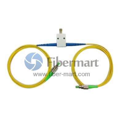 Need for optical fiber amplifiers
Optical amplifier EDFA solves the traditional distance problem as in any long-distance telecommunication system such as a trans-Atlantic link. The signals become weaker in power because optical signals travel through the fiber. The signal become weaker if you go far until it becomes too weak to be detected reliably. Optical fiber amplifiers and their working An optical fiber amplifier is a part of optical fiber that is doped with a rare-earth element such as erbium or praseodymium. By high power light (pump laser) the atoms of erbium or praseodymium can be pumped into an excited state. But in the excited state, they are not at all stable. When there is a need for optical signals to be amplified then it is required that they should pass through the fiber as they stimulate the excited erbium atoms. The erbium atoms will then jump from the high-power level excited state into a low power level stable state, and at the same time, it releases their energy in the form of emitted light photons. Like the input optical signal, the emitted photons have the same phase and wavelength thus amplifying the optical signal. This is a very convenient form of the amplifier, especially for an optical fiber communication system as it is an in-line amplifier. It then removes the need to do the optical-electrical and electrical-optical conversion process. Cooperation of fiber optical attenuator pumps the laser wavelengths and the corresponding optical signal wavelengths are key parameters. These wavelengths rely on the type of rare-earth element doped in the fiber and also on the composition of the glass in the fiber. Gain is another important term in understanding fiber amplifiers. The amplification per unit length of fiber is measured in gain. The gain depends on both the materials and the operating conditions, and it differs with wavelength for all materials. In the case of low input powers, the output power is proportional to the gains times the fiber length. The gain saturation effect comes into play for high input powers. So, an increment of input power produces less and less output power, which means that the optical switch has run out of the power it needs to generate more output. Follow our Facebook and Twitter for more information about our product. 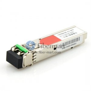 SFP stands for small form-factor pluggable and transceiver refers to a device that can both transmit and receive data. This article SFP Transceivers Explained is used to describe all about finisar SFP transceivers in detail that helps networking professionals understand SFP optics and its types.
The SFP transceiver is a compact, hot-swappable device that gets easily plugged into a physical port of a network device. In communication networks, SFP optics are used and it consists of a transmitting side (Tx) and a receiving side (Rx). The transceiver consists of a laser that communicates to the receiving side of the other optic. The designing of SFP optics is done to support several communication standards including SONET, Gigabit Ethernet, and Fiber Channel. On networking devices such as routers, there is the interfacing of SFP and it provides a modular interface that can be readily adjusted to fiber optic and copper networking specifications. The SFP is also referred to as mini GBIC. GBIC is the Gigabit Interface Converter (another transceiver model) and due to the smaller size of SFP than GBIC, it is called mini GBIC. SFP came into existence much later than GBIC and it serves the same purpose as the GBIC module but because of its smaller size, in most applications today SFP has replaced the GBIC. Unlike GBIC which generally comes with the SC (Standard connector), SFP usually comes with the LC connector (Lucent connector). LC and SC connectors are fiber-optic cable connectors that are differentiated based on their sizes. Things You Need to Check with SMF and MMF SFPs:
Follow our Facebook and Twitter for more information about our product. |
AuthorWrite something about yourself. No need to be fancy, just an overview. Archives
June 2024
Categories
All
|
 RSS Feed
