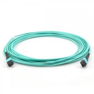
 MPO and MTP cables are both multi-fiber connectors intended for high-density fiber optic connectivity. MPO is a generic word for multi-fiber connections, whereas MTP is a brand name for a prominent producer of optical fiber connectors. While MPO and MTP cables are frequently used interchangeably, MTP cable is a proprietary variation of the MPO connection.
The Advantages of MPO and MTP Cables
MPO and MTP Cable Applications MPO/MTP cables are used in a variety of sectors and industries, including:
Follow our Facebook and Twitter for more information about our product.
0 Comments
 A few issues must be resolved to guarantee ideal performance and signal quality. Controlling the transmitted signals' power levels is one of these difficulties. Attenuators for fiber optics are useful in this situation. The goal, varieties, and advantages of fiber optic attenuators in improving signal quality in optical networks will all be covered in this blog.
A fiber optic attenuator: what is it? To lower the power of an optical signal, fiber optic attenuators are passive devices used in optical networks. To regulate the light intensity, a generally tiny, discrete device is put into the fiber optic link. The device guarantees that the transmitted power is within acceptable ranges by attenuating the signal and preventing signal deterioration, distortion, or failure altogether. Fiber optic attenuator types: These attenuators, which normally come in various increments, give a set degree of attenuation. They are frequently employed in situations where a particular amount of attenuation is required since they are easy to use, affordable, and simple. Attenuation levels can be adjusted with variable attenuators, as opposed to fixed attenuators. They are frequently employed in settings involving testing, calibration, or troubleshooting and offer more flexibility in adjusting signal power levels. Attenuators that are built right into fiber optic cables, known as inline attenuators, provide a smooth way to lower power levels without the use of extra connections, fiber couplers, or adapters. They are frequently utilized in installations with high densities or when there is a shortage of space. Attenuators that combine the characteristics of both fixed and variable attenuators are known as hybrid attenuators. They initially offer a set amount of attenuation but also permit subsequent alterations if necessary. They are excellent for a variety of applications due to their adaptability. Fiber optic attenuators' advantages include: Fiber optic attenuators ensure that transmitted signals stay within the ideal power range, preventing over- or under-driving of receivers. As a consequence, bit errors are decreased, signal quality is improved, and data transmission dependability is increased. Network Flexibility: Attenuators provide network engineers the ability to modify signal power levels, allowing them to improve performance and efficiently fix problems. They can account for variable device sensitivities, varying link lengths, and modifications to network setups. Equipment Protection: Attenuators shield delicate network components from high light intensity by controlling signal power levels. By preventing damage to transmitters, receivers, and other optical equipment, their lifespan is increased and maintenance expenses are decreased. Attenuators and fiber splitter are cost-effective options for signal power control since they do not require expensive equipment upgrades or reconfigurations. They offer an easy and effective way to obtain the appropriate power levels without making a big investment. Follow our Facebook and Twitter for more information about our product. 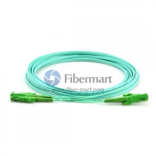 In data centers and other high-performance computing settings, MTP and MPO cable are two varieties of fiber optic cables that are often utilized. These cables are intended to offer high-bandwidth applications like cloud computing, virtualization, high-speed data transfers quick, dependable communication.
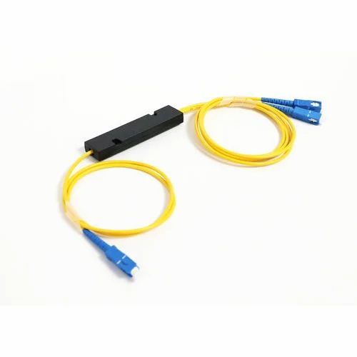
The fiber optic connector type known as MTP, or "Multifiber Termination Push-On/Pull-Off," enables the termination of several fibers in a single connector. Switches, routers, and servers in high-density data centers are frequently connected via MTP cables. Also, they are employed for fiber-to-the-desk (FTTD) applications, which call for quick connections between desktop PCs and the technology in data centers. MPO, which stands for "Multifiber Push-On," is a comparable kind of fiber optic connector that also enables the termination of several fibers in a single connector. MPO cables, on the other hand, are frequently employed for longer-distance applications, such as fiber-optic backbone networks that link several data centers or substantial structures. The rapid data transfer speeds of MTP and MPO cables are one of their main benefits. These cables are perfect for high-performance computer applications since they can handle data speeds of up to 100Gbps or more. Moreover, MTP and MPO cables provide minimal insertion loss and excellent return loss characteristics, making them extremely dependable. As a result, even in loud or busy surroundings, they can sustain good signal quality across extended distances. You can buy PLC splitter online. Moreover, MTP and MPO cables are quite adaptable, offering a variety of choices for various connection types, fiber kinds, and cable lengths. They are therefore suitable for a wide range of applications, from straightforward point-to-point links to intricate, multi-layered network topologies. MTP and MPO connections are fundamental parts of contemporary data centers and high-performance computing settings, to sum up. These cables offer quick, effective, and dependable communication for a variety of applications because of their high data transmission speeds, dependability, and adaptability. MPO and MTP cable are great options whether you're establishing a new data center, updating your network infrastructure, or just searching for faster, more dependable connectivity for your high-performance computing applications. Follow our Facebook and Twitter for more information about our product. 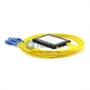 A PLC splitter, also known as a planar waveguide circuit splitter, is a device that divides or combines multiple light beams into one or two uniformly distributed light beams. This passive optical device, which connects the MDF (main distribution frame) and the terminal equipment and branches the optical signal, is particularly useful for PON. It has a lot of input and output terminals.
A low-cost light distribution solution with excellent stability and dependability is offered by PLC splitters. PLC splitters, a common form of optical splitter, may offer a splitting ratio of up to 1x64, which is often higher than the splits of FBT splitters. Manufacturing Technology for PLC Splitters PLC splitter uses semiconductor technology as its foundation. PLC splitters are produced using planar waveguide circuit technology, as their name implies. Depending on the output ratio, the PLC splitter architecture comprises one optical PLC chip and several optical arrays. On both ends of the PLC splitter chip, there is a coupling of the optical arrays with the fiber coupler. PLC splitters are classified. PLC Fiber Optic Splitters can be divided into 1xN and 2xN PLC splitters, such as 1x4 splitter, 1x8 splitter, 1x16 splitter, 2x32 splitter, 2x64 PLC splitters, etc., depending on the PLC splitter chip they use. Input and output numbers can be changed by users based on cable length or subscriber conditions. To satisfy the demands of customers in various contexts, PLC splitters may also be categorized based on different packages. Examples include small-size PLC splitters that must be used in terminal boxes and large-size rack-mounted PLC splitters that can be put in racks. PLC splitters come in five different varieties: Rack-Mount Splitter, Blockless Fiber Splitter, LGX Splitter, ABS Splitter, and Bare Fiber Optical Splitter. With a PON Network, How Does a PLC Splitter Operate? A PLC fiber splitter is frequently positioned between the PON Optical Line Terminal (OLT) and the Optical Network Terminals/Units (ONTs/ONUs) that the OLT serves in passive optical networks (PON). The input of a splitter is linked to the single fiber connection exiting the Central Office (CO) OLT, which is split into a certain number of fibers. The number of splits depends on the number of outputs in the PLC module. PLC splitters may be utilized in either a distributed or centralized PON design. 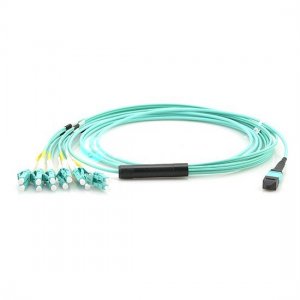 To ensure the 5G New Radio Metro Transport Network, the number of connections using MPO cable structure will rise in the upcoming years. LC to LC Simplex and Duplex connections are also frequent and simple to connect. MTP MPO cable, on the other hand, is more complicated and calls for a fundamental understanding of key characteristics and application scenarios. The goal of this support page is to give readers the fundamental knowledge they need to comprehend MPO-8, MPO-12, or MPO-16 cables, as well as Key A or Key B, Type A or Type B, Trunk, and Breakout cables. This enables smoother and speedier project design, ordering, and installation procedures, cutting costs and enhancing efficiency.
Cables MTP MPO MTP MPO cables are now interchangeable. They are not interchangeable, though. An improved variant of MPO cable is MTP cable. First of all, the MTP connection includes a detachable casing that enables cleaning, repair work, and connector head replacement. To prevent the cable from being easily snapped inside the connection housing, it also incorporates a more sophisticated mechanical support mechanism. To be sure, detachable housing is not guaranteed, but several MPO has included comparable mechanical Support and offer breaking resistance from heavy bending stress. Push-On Multi Fiber Connector The connection is a good place to start since it makes it simple to tell a cable apart. There are numerous other varieties, including, mentioning a few, LC, SC, and MT-RJ. Multi-Fiber Push On (MPO) connections are relatively new and often used. However, as more and more data lanes are needed to meet the needs of 400G Ethernet, the demand for and utilization of MPO will increase. Consolidation and compact cross-connection throughout the infrastructure are made possible using MPO Trunk cable. They are frequently utilized in corporate, campus, telecom, and data center networks. Furthermore, MPO Trunk cables offer incredibly high density, high-quality transmission performance, and extremely minimal signal loss. This cannot be emphasized enough. Consider 1:1 connections with both sides being 40G, 100G, 200G, 400G, or even 800G while thinking of MPO cable. What enters via one end will exit through the opposite end. It is necessary to match the Trunk Cable fiber count to that of the Transceiver or other Equipment on both ends to establish a strong connection. Follow our Facebook and Twitter for more information about our product. 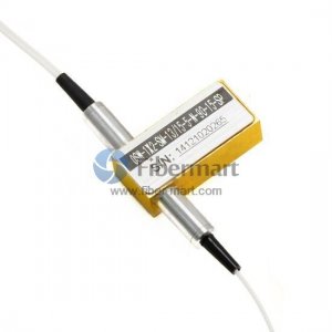 Fiber optics is a practical instrument that is frequently utilized in the domains of engineering and applied sciences for the transfer of data across great distances. Optical fibers are translucent, bendable strands of silica, or pure glass. Fiber optic cables, which are as thin as human hair, serve as a waveguide to carry light between the two ends of the strand. Due to their reduced transmission loss and resistance to electromagnetic interference, these cables are favored over metal wires. A clear core and a transparent cladding material with a reduced index of refraction are the basic components of optical fiber. Total internal reflection keeps light inside the core. The fiber now functions as a waveguide. You can buy fiber polisher online.
The caliber of the fiber and the clarity at either end of the transmission line is crucial to the effectiveness of fiber optics. The cut ends of the wires need to be polished smoothly to maximize efficiency and data transfer rate. The development of fiber optic polishing devices has advanced significantly during the past several years. Companies that rely on these cables now have access to a complete industry that caters to their demands. Within the fiber polishing machine, some businesses polish fiber ends on-site, and others design and provide the highly specialized polishing equipment needed for the job. When measuring elements like apex offset, the radius of curvature, fiber protrusion, back reflection, and under-cut, optical fiber polishing machines are capable of the tight tolerances and precise repeatability needed to continuously deliver outstanding manufacturing outcomes. Yield and throughput are two crucial elements to consider when choosing optical fiber polishing equipment. Yield is a measure of consistency and quality. Productivity is gauged by throughput. The greatest of these tools enables platen force, speed, and time adjustments to meet exact requirements and accurately polish fiber optic connection ends in a repeatable, dependable way. For a variety of uses, specific polishing materials and fiber optical switch have also been created in addition to highly developed and programmed polishing equipment. These substances, sometimes known as abrasive films, are made to produce extremely exact polishing results.  We utilize optical amplifier EDFA in fiber optic transmission to boost signal electricity, which seems to be a typical practice. The amount of light that is delivered through a fiber optic receiver, however, may occasionally be too much and should be lowered. In this situation, a part known as a fiber optic attenuator can aid in lowering the signal's power level. This article will concentrate on providing a detailed description of the fiber optic attenuator from the standpoint of its varieties and uses.
A passive device used to lower an optical signal's power level is a fiber optic attenuator, sometimes referred to as an optical attenuator. It can be used in an optical fiber or free space. Additionally, using a fiber optic attenuator in single-mode long-distance applications helps to reduce the possibility of optical overload at the receiver. The fiber optical attenuator effectively lowers the signal's power through absorption, reflection, diffusion, scattering, deflection, diffraction, and other processes. Optical attenuators typically work by absorbing light, much like sunglasses do when they take in excess light energy. There is a practical wavelength range where they equally absorb the light energy. Since doing so might lead to undesirable back reflection in the fiber system, they shouldn't reflect the light. Fiber optic attenuators can be used to temporarily introduce a calculated amount of signal loss to verify power level margins. Additionally, it is frequently permanently installed to properly align the levels of the transmitter and receiver. The fixed attenuator is intended to have a constant level of attenuation, as its name indicates. Theoretically, it could be built to offer any required level of attenuation. Fixed attenuators fall into two categories: in-line type and connector type, and they are frequently employed for single-mode applications. The in-line type looks like a regular fiber patch cable with two connectors at each end of the fiber. A variable neutral density filter is typically used with variable optical attenuators. It benefits from stability, wavelength insensitivity, mode insensitivity, and a wide dynamic range. Variable optical attenuators are frequently used in EDFAs to balance the light output across several channels. They are typically utilized for testing and evaluation. The two main varieties of variable attenuators are stepwise and continuously variable attenuators. You can buy optical switch online. Follow our Facebook and Twitter for more information about our product. 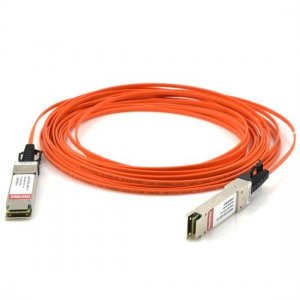 Quad Small Form-factor or QSFP cable IO interface interconnects have traditionally been made up of pluggable connectors and wires. The four-lane design is often used to link server, storage, switch, video, and communication systems. Cloud data centers, business data centers, HPC (high-performance computing) laboratories, video surveillance systems, Internet provider systems, and machine vision systems are some of the major market segments that have implemented these technologies.
The previous CX4 SFF- 8470, another four-lane connector used for 10 G Ethernet IEEE802.3ak, InfiniBand SDR 42.5 G, and DDR 45 G, as well as Fibre Channel ISL 48 G, was eventually replaced by this first generation QSFP connectivity technology. The QSFP receptacle connection contains stamped copper contacts, but the cable plug is a PCB with plated pads, whereas CX4 is a two-piece copper contact connector system. In general, mated QSFP connections are less expensive than CX4 connectors, and the plug PCB enabled the addition of active chips for reaching objectives with faster data rates. There are still some CX4 connections and cables in use, particularly when servicing an existing equipment base. Different data speed rate transceiver modules are used with the QSFP28 cable, and they are plugged into the receptacle edge-style connector that is inboard from the box bulkhead and beneath a QSFP metal shield cage. The backside of the module rests flush on the back panel or bulkhead of the box. The small module's outboard end frequently has an MPO or MXC receptacle connector that facilitates mating connection with a variety of external fiber-optic cable types, depending on the requirements of the link reach. AOMs, or Active Optical Modules, come in a wide variety of power consumption, price, speed rates, reaches, and photonic technology. For EMI control and EMC compliance, SFP cable are often built employing eight independently protected twin-axial transmission components within an outer shielding layer. The differential pair shields, system shields, and copper wire conductors are meticulously prepared, processed, and either laser welded or reflows soldered to the PCB pads. In the past, longer cable length reaches required the temporary usage of exceptionally large 22 AWG wire-size cables due to quicker data rate increases. Since then, the demand for copper reach lengths has drastically decreased, and certain short applications now make use of exceedingly small twin-axial components composed of 33 AWG wire, which makes the outer diameter cable size more acceptable. Original source: https://fibermarts.wordpress.com/  Standard transceivers are the simplest way to connect 100G traffic, and a large variety of cables and transceivers are compatible with this. Ethernet switch manufacturers seek to pack as many optical transceiver ports as possible onto their hardware to provide customers with rack or data center connections that are both cost-effective and efficient. This enables them to provide the highest channel count and the lowest cost per bit of traffic.
The cisco QSFP28 transceiver is the smallest form factor transceiver that the majority of these switch vendors use. It is the smallest module currently on the market and uses the least amount of power among those that can handle 100G traffic. Another noteworthy fact is that the QSFP28 is physically identical to the QSFP+ frequently used for 40G traffic. As a result, switch manufacturers can boost traffic throughput by a factor of 2.5 without having to change their switches' front panels. cable assembly for QSFP28 The use of cable assemblies not only requires fewer components but also eliminates several issues brought on by unclean connections. 0 to 15 meters of DAC (Direct Attached Cables) and 70 meters of AOC (Active Optical Cables) are available. Comparable performance is offered by AOC cable assemblies, fiber cables, and standalone transceivers. TRANSCEIVERS QSFP28 Short-range cisco QSFP -SR4 transceivers enable communications over multimode fiber of up to 100 meters. Similar to employing AOC cables, this method also allows for the usage of structured cabling. Some of the transceiver's cost reductions are offset by its usage of more expensive non-standard MPO (multi-push-on/pull-off cable) connections. The good news is that the switching supplier will now be able to manage data that stays in the data center and rack. The QSFP28 provides the ideal match for these circumstances. It only becomes a concern when 100G traffic needs to be sent across considerable distances, as is the case when connecting 100G data centers in various places. The size and power are still needlessly large, and frequently unreasonably so, even if a manufacturer opts for the lesser CFP2 or CFP4. Offering CFP DWDM capability for the few connections that require it is one approach, but even then, the increase in power consumption and the reduction in available ports affect the switch's overall cost-effectiveness. You can buy cisco SFP online. 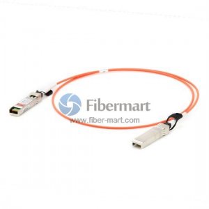 Applications for SFP cable are numerous. However, they can fail to perform in the manner for which they were designed. If this occurs, it could be a good idea to figure out why the SFP module is malfunctioning. This tutorial can help by offering a variety of remedies if you are new to the transceiver industry and your module malfunctions.
Compatibility problems are the blame for SFP transceivers failing. Issues with Compatibility The majority of manufacturers promise complete compatibility, albeit this may not always be the case. The item may not work in some cases, and you may find yourself debugging it ineffectively. If this occurs, finding a solution could be harder and need more technical expertise than what a normal beginner might have. If any component of your infrastructure is older, there's a good probability the new transceiver was made using modern manufacturing techniques. Therefore, it is advised that you think about replacing the equipment. Establishing Compatibility Most transceivers feature a burned-in chip that contains data like the serial number, security information, and vendor ID to identify compatibility problems. The device will be deactivated and cease to function if the information provided does not match that in the database. You can buy QSFP28 cable online. Faulty components The transceiver's parts might occasionally burn out too soon. This might happen with a lot of problems. The majority of suppliers frequently incorporate an automated shutdown of the complete machine in the event of a failure. The wear and tear might also cause the transceivers to cease functioning. It is advised to do a thorough analysis to identify the issue if any transceiver component malfunctions. Sometimes it is preferable to purchase a new SFP transceiver rather than attempt to repair a damaged one. A lot of dust Dust shouldn't be allowed to get near optical equipment. When not in use, always insert the SFP and QSFP cable inside a dust plug. Dust buildup on the LC connections may cause the module to stop functioning suddenly. Dust interferes with the transmission of signals, causing the optical transceiver to malfunction. |
AuthorWrite something about yourself. No need to be fancy, just an overview. Archives
June 2024
Categories
All
|
 RSS Feed
